

Keel slot casing and capping on Enfys (photo: Bill Dowell)
The structural elements that enclose a Finesse swing keel provide many routes for unwelcome leaks.
(A) Ballast keel bolts. The external ballast keel is held on by 13 bolts which necessarily pass through from the wet side to the inside of the boat. Three of these are forward of the swing keel structure and two are behind it (and under the engine). Of the remaining eight, four are placed in two pairs on either side of the keel case and four are in two pairs under the slot capping. Any upward seepage alongside these bolts will cause wasting in the long term and, as they get thinner, water can begin to weep into the boat.
The main photograph (above) shows the thin piece of slot capping removed and placed top right. Underneath the capping, the structural sandwich is revealed. Two long keelson timbers run fore and aft either side of the slot; between them is wedged a third timber, which fills the top of the slot. The sandwich is bolted together athwartships. The joint between the sides and the central timber is very hard to make out in this picture as they are a face-on-face fit.
Each of the keel bolt nuts is hidden below a 1.5″ diameter dowel cap which will need to be destroyed to gain access to the nut below.
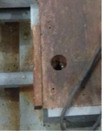
Keel bolts are recessed into the keelson timbers and covered by dowels (not shown)
If you see evidence of weeping from beneath the capping, remove it (it is held down by woodscrews) and look to see if the source of the water is the location of one or more bolts. If any are weeping, their replacement is a very hard job and (IMHO) is best delegated to a specialist boatyard like Alan Staley or Robertsons. However- there are other candidates for leaks in this area:
(B) The junctions in the keel slot sandwich
The long joints in this construction will weep if the adjacent faces are not a perfect fit. In theory, the athwartships bolts can be tightened but this may not look feasible after many decades. I treated a leak by routing a ‘V’ slot along the length of each joint and then
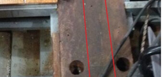
These red lines show the long face to face joints in the timber sandwich. This whole structure is part of the hull and needs to be water-tight
filling the slot with very slow two-part epoxy; by the time it had set, my theory was that it would have crept down any gap(s) in the joint. When it comes to replacing the capping, remember that this is part of the hull construction and attention must be paid to proper sealing. I used a non-setting flat roof black sealant on the sandwich, and then applied a layer of cling-film under the capping to make it easier to remove it in the future.
(C) The keel case

Base of the keel case. The upstand are inside the case construction.
The sides of the case are set against the upstands on the keelson timbers and are another example of the water-tight potential of face-on-face flat timbers. If there is evidence of water weeping from the keel bolts under the sides of the keel case, the news is even worse than for the bolts under the capping- the keel case will need to be removed and rebuilt.
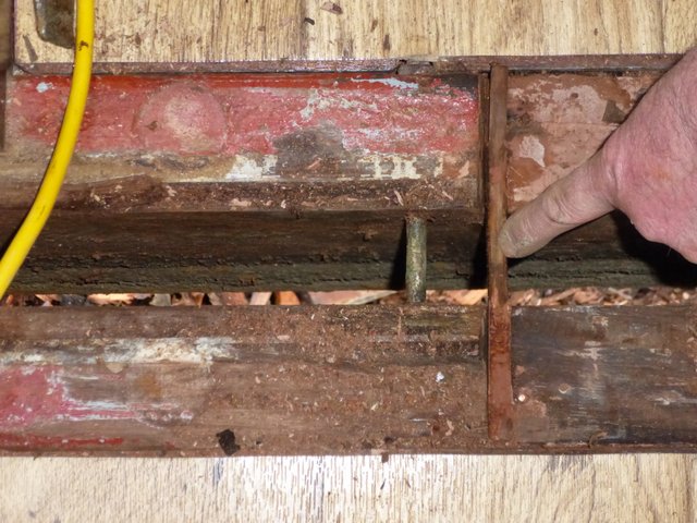
(D) The stop-water
Stop-water from above. One of the sandwich athwartships bolts can be seen. Under that is rubble on the boatyard floor.
The junction between the capping and the front of the keel case contains (in the original construction) a softwood dowel. This junction is expected to weep, and the dowel is intended to absorb water, swell and hence stop the leak. If this construction is in good condition, then leaks here should stop of their own accord.
The lower part of the keel case is permanently under water and the fact that it works at all is down to careful design and good workmanship. I interfered, to my cost, a few years ago. I decided that I would insert a bolt through the keel case sides, near the top (above the waterline!) that would pass through the keel blade as a back-up in case the winch cable failed. Then one day we were reversing hard to release from some weeds near a riverbank; it turned out that the prop, running in reverse, could push water under the boat and up through the case, through the bolt holes and onto the seat cushions. This unwelcome flooding was repeated later on out on the Wash when short sharp chop pushed water up into the keel case. Lesson learned: the case needs to be water-tight above and below the water-line.
Propeller box

Stuffing box (source: Cox Engineering http://coxeng.co.uk/stern-gear/stern-glands/)
Water ingress where the propeller shaft passes though the hull should be carefully managed. Typically a soft packing material is compressed around the prop shaft and lubricated with grease. Not only is it difficult to achieve zero leakage at this point, it is often considered to be useful to have a slow drip rate when the shaft is rotating as the water is the coolant for the seal. Grease is not to be thought of as the sealant. The rate of drip (which should be zero when the prop is not rotating) should be managed by adjustment of the gland nut, compressing the packing until the drips cease but the prop shaft can easily rotate. Too much grease can overheat the packing, and excess grease will be squeezed out and emulsified into the bilge water under the engine. The adjustment of a variety of glands is discussed in this excellent resource from Cox Engineering: Stern glands – Cox Engineering
Holes below the waterline
Most boats have gadgets thrust though their hulls- depth sounders, paddle-wheel speed transducers, sea toilet fittings. These should not leak, at all, ever. In addition, make sure (for example, in the heads) that you can’t give the fitting a good kick with your toe by mistake.
Holes above the waterline
There are also holes above the waterline: exits for the bilge pump(s), engine exhaust, sink drain etc. There are some minor ones (a drain for the gas locker, a vent for the fuel system) that must remain open, but the others should be fitted with manual lock-off valves- if you sail at extreme angles, some of these won’t be above the waterline after all!


When we dismantled ‘Enfys’ centreboard casing to do the keelbolts we didn’t find a stopwater in the joint as shown in the article..